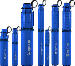
| |||
APPLICATIONA centrifugal electric pump unit of ECV type for wells is intended for feeding water with general mineral content (solid residue) within 1500 mg/l, with pH ranging 6,5 to 9,5, the temperatures up to 257°C and with hard mechanical impurities below 0,01% by mass, the chloride content - not more than 350 mg/l, sulfate content - not more than 500 mg/l, hydrogen sulfide - not more than 1,5 mg/l.They are used for urban, industrial and agricultural water supply and irrigation as well as for the ground-water lowering. PUMPING UNIT DESIGNATION
ECV - unit type (submersible electric motor, centrifugal pump for supply of water) 8 - the maximum permissible inner diameter of the casing string (well) for this standard size, (inch) 25 - flow rate (m3/h) 100 - head (mwc) For pumps which operate from the chemically active water, water of high temperature or water with high concentration of solid mechanical impurities the garphic symbols must include the letters H, Tr, G, HTr, HTrG:
DESCRIPTION AND OPERATIONThe unit consists of a centrifugal pump and submersible electric motor. The shafts of the pump and the engine are connected by rigid coupling. Accurate treatment of the mated surfaces ensures that the shafts are in line with each other. The pump is, as a rule, of multistage, vertical design.The axial forces arising at work of the pump are taken by the thrust bearing of the motor. The valve, located in the top part of the pump, keeps the column of liquid in the water-rising pipes when the pump is stopped and provides smooth start at repeated start-ups. The pump is joined to the water-rising pipes by means of tapered thread or by flanges. The rubber-mechanical bearings and seals are lubricated and cooled by water. That is why the pump will be made inoperative if not immersed in water. Before starting the three-phase squirrel-cage sinking electric motor, its interior chamber is to be filled with distilled or boiled drinking water. Switching on of the engine not filled with water will result in putting it out of operation. The winding of the engine is made of waterproof wire; connections are insulated by waterproof sticky tape. The rotor of the engine rotates in rubber-metal bearings and rests on a thrust axial bearing that is made of rubber or graphite-fluoroplastic. The filter in the top part of the engine protects the interior chamber against sand getting in it and also compensates for thermal expansion of water filling the engine. CONTROLThe unit is operated by a system of automatic control (complete equipment of the SUZ, KASKAD, VYSOTA kind). The unit may not be turned on more than three times within an hour with the intervals between them not less than five minutes.Joint operation of two or more units is not permitted for a single pressure pipeline or with a single automatic control system. It is not recommended to keep an idle (inoperative) unit in water for a long time (more than 7 days). |
| | | HOME | | | PRODUCTS | | | SITE MAP | | | HOW TO FIND US | | |
