|
|
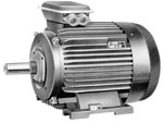
THREE-PHASE INDUCTION MOTORS WITH SQUIRREL-CAGE ROTOR FOR GENERAL INDUSTRIAL USAGE: AIR and 5A SERIES
TECHNICAL CHARACTERISTICS
|
|
|
|
|
Three-phase induction motors with squirrel-cage rotor include:
- Motors of the main (basic) design;
- Motors with the power capacities and mounting sizes of the CENELEK export standards;
- Motors with uprated sliding action for mechanisms with pulsating loads, of great fly masses and for mechanisms with frequent start-ups.
DESIGNATIONS
The motors are marked as follows:
- Series markings (AIR or 5A).
- Sign of "extra-sliding" modification (S).
- Dimensions (shaft height, mm).
- Mounting dimension according to the length of frame (S,M,L).
- Length of core with mounting sizes preserved (A,B).
- Number of poles.
- Sign of power capacity relative to mounting sizes according to the CENELEK standards (K).
- Climatic design by the RF GOST 15150.
STANDARDS
Induction motors of AIR and 5A series
for general industrial usage (basic design and its modifications)
meet the following standards requirements:
|
| NAME | STANDARDS of RF | PUBLICATION IEC |
| Rotational electric motors.The data-sheet value and operating characteristics. | GOST 28173 | IEC 34-1 |
| Induction electric machines with power capacity of 1 to 400 kW. Motors. The main technical demands. | GOST 28330 | |
| Rotational electric machines. Nominal rates of power, voltage and frequencies. | GOST 12139 | IEC 38 |
| Rotational electric machines. Installation overall size. | GOST 18709 | IEC 72 |
| Rotational electric machines. Classification of protection degrees ensured by casings of rotational machines. | GOST 17494 | IEC 34-5 |
| Rotational electric machines. Ways of cooling. Markings. | GOST 20459 | IEC 34-6 |
| Rotational electric machines. Symbolic markings for construction forms according to ways of installation. | GOST 2479 | IEC 34-7 |
| Rotational electric machines. Markings of outlets and rotational direction. | GOST 26772 | IEC 34-8 |
| Rotational electric machines. Permissible noise level. | GOST 16372 | IEC 34-9 |
| Rotational electric machines. Built-in temperature protection | GOST 27895 | IEC 34-11 |
| Rotational electric machines. Starting characteristics of one-speed three-phase induction motors with short-circuited rotor, voltage up to 660V. | GOST 28327 | IEC 34-12 |
| Rotational electric machines. Vibration permitted. | GOST 20815 | IEC 34-14 |
| Insulation system. Heat resistance assessment and classification.. | GOST 8865 | IEC 85 |
| Electromagnetic compatibility of technical means. Induction motors, voltage up to 1000V. Norms and methods of testing resistance to electromagnetic interference. | GOST 50034 | IEC 1000.2-1 |
|
|
up
|
DEVIATIONS
According to GOST 28173 (IEC 34-1) the nominal ratings of electric motors, presented in the database, may have some deviations, as listed below:
|
| PARAMETR | DVIATIONS PERMITTED |
| Efficiency, η | |
| machines with power up to 50kW inclusive | -0,15 x (1-η) |
| machines with power more than 50kW | -0,10 x (1-η) |
| Power factor, cos φ | - (1 - cos φ)/6
min: -0,02
max: -0,07 |
| Sliding, S | |
| machines with power up to 1kW | ±30% of guaranteed value |
| machines with power of 1kW and more | ±20% of guaranteed value |
| Initial starting current | +20% of guaranteed value |
| Setting point (with rotor locked) | from -15% to +25% of guaranteed value |
| Minimal rotational moment at starting | -15% of guaranteed value |
| Maximum rotational moment | -10% of guaranteed value, but no less then 1,5 of nominal moment |
| The dynamic moment of rotor inertia | ±10% of guaranteed value |
|
|
DESIGN Motors of 5A, AIR and 6A series are made in accordance with the way of installation, depending on the overall dimensions. The symbolism for the design meets GOST 2479 (IEC 34-7) requirements.
The initial figure - indicates the construction of the motor:
1-electric motor on feet with bearing shields;
2-electric motor on feet with bearing shields and a flange on a bearing shield.
3-electric motor without feet with bearing shields and a flange on a bearing shield.
5-electric motor without frame, bearing shields or shaft.
The second and third figures indicate the way of mounting of electric motor (see the table below).
The fourth figure indicates the design of motor shaft:
1-with one-cylindrical shaft end;
2-with two-cylindrical shaft ends (made to order to suit the customer's requirements).
|
| Construction form | Marking | Application rage according to dimensions | Construction form | Marking | Application rage according to dimensions |
| IM 1001 (IMB3) |  | 80-315 | IM1011 (IMV5) |  | 80-250 |
| IM 1031 (IMV6) |  | 80-250 | IM1051 (IMB6) |  | 80-250 |
| IM 1061 (IMB7) |  | 80-250 | IM1071 (IMB8) |  | 80-250 |
| IM 2001 (IMB35) |  | 80-315 | IM2011 (IMV15) |  | 80-250 |
| IM 2031 (IMB36) |  | 80-250 | IM2101 (IMV34) |  | 80 |
| IM 2111 (IMV15) |  | 80 | IM2131 (IMV36) |  | 80 |
| IM 3001 (IMB5) |  | 80-180 | IM3011 (IMV1) |  | 80-250 |
| IM 3031 (IMV3) |  | 80-250 | IM3601 (IMB14) |  | 80 |
| IM 3611 (IMV18) |  | 80 | IM3631 (IMV19) |  | 80 |
|


